Bonding With Masonry: Tech Talk Q3
Words: David Biggs
By David Biggs
This issue’s questions come from an Architect, a General Contractor, and an Engineer. What questions do you have? Send them to info@masonrymagazine.com, attention Technical Talk.
Q. An Architect writes that their standard details have always shown truss-type horizontal joint reinforcement in single-wythe and cavity CMU walls. However, most masons object to its use. Isn’t joint reinforcement required for crack control?
A. Thanks for the question. You are correct that horizontal joint reinforcement is a preferred method for crack control. NCMA recommendations are to use either joint reinforcement or reinforced bond beams. There are three NCMA TEK notes, TEK 10-02D, Control Joints for Concrete Masonry Walls—Empirical Method, TEK 10-03, Control Joints for Concrete Masonry Walls – Alternative Engineered Method, and TEK 10-04, Crack Control for Concrete Brick and Other Concrete Masonry Veneers regarding crack control.
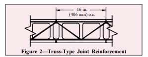
The likely reason masons have objected to the use of truss-type reinforcement is that you are requiring it in reinforced CMU walls. Truss-type reinforcement is not recommended in vertically reinforced walls because the diagonals of the truss could interfere with the placement of vertical bars; ladder-type joint reinforcement is the preferred joint reinforcement product for vertically reinforced walls. Preferably, truss-type reinforcement should be limited to unreinforced CMU walls and veneers. This is noted in NCMA TEK 12-02B, Joint Reinforcement for Concrete Masonry which states “Because the diagonal cross wires may interfere with the placement of vertical reinforcing steel and grout, truss-type joint reinforcement should not be used in reinforced or grouted walls.”
Figure 2 from NCMA TEK 12-02B shows the diagonals that can interfere with vertical bar placement and grouting in the cells.
Summary:
- Horizontal joint reinforcement is a recommended option for crack control in CMU walls; reinforced bond beams can also be used.
- Truss-type horizontal joint reinforcement is only recommended for unreinforced walls and veneers.
- Ladder-type horizontal joint reinforcement can be used in all conditions.
Q. A General Contractor received an RFI from their Mason subcontractor. The project is a pre-engineered metal building with infill cavity walls of CMU and brick veneer that are braced to the building frame. The mason asked for the anticipated drift (sidesway) of the metal building under wind loads and earthquake loads.
The project architect and engineer delegated the design of the building frame to the pre-engineered building supplier.
A. This is an interesting question and an astute one by the Mason contractor. Without reviewing the drawing notes or specifications by the architect and engineer, I can only assume the Mason did not find the drift limitations in any of the documentation. If limitations are not accounted for in the design of the masonry, building drift and deflection of the framing can cause cracking in the attached walls, exterior and interior. That cracking if not understood, might be incorrectly attributed to the work of the Mason rather than a design issue. So, it was appropriate for the mason to ask for the information.
The Metal Building Manufacturers Association (MBMA) represents the metal-building industry and publishes “Metal Building Systems Performance Guide Specification.” It acknowledges that masonry walls are a common wall system for their buildings, and they offer the following:
“Specifiers Note: Refer to the IBC (Table 1604.3) for further information on deflection limits. As discussed in AISC Design Guide No.3, the drift limit is primarily selected based on the flexibility of the attached wall materials. H/60 or H/100 is common for metal wall panels but more brittle walls such as masonry, concrete or glass may require lower allowable drift limits. The proper drift limit is important for performance as well as economical framing.”
The guide specification lists various criteria that should be specified by the building designer. One related to masonry states:
“Deflections shall be limited as follows:
L/[90] [ ] for 10-year wind load on wall girts.”
The girts [and spandrels] are elements that brace the walls against lateral loads. The designer either accepts the L/90 limit or selects their own and inserts it into [ ]. For example, using L/90, the deflection of a girt on a 20-foot bay spacing could result in a 2.67-inch deflection which would be considered excessive for the masonry. So, specifying an alternate value to the 90 would be advisable.
The second states “
“Drift shall be limited as follows:
[H/60], [H/100], [H/200], [H/400], [ ] for 10-year wind load.”
MBMA gives several options to choose from. The designer again selects one value or develops their own [ ]. The drift applies to the building frame.
The Concrete Masonry and Hardscape Association (CMHA), formerly NCMA, has a document titled “Concrete Masonry Walls for Metal Building Systems” which specifically addresses the interaction with metal buildings. It is reasonable to use the criteria with clay brick also.
Figure 2.1E shows the masonry spanning full height to a spandrel. Partial height masonry walls would be supported at the top by a girt.
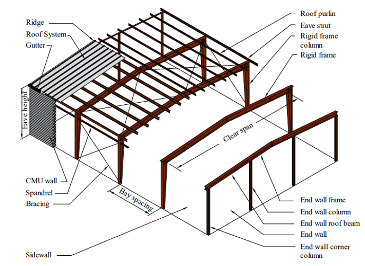 Figure 2.1E—Schematic of Metal Building Clad with Concrete Masonry Walls
(Courtesy of CMHA)
The document is silent on recommendations for girt deflection. TMS 402 also is silent. The closest info we can find is L/300 to L/600 relative to unreinforced masonry supported vertically on framing. The specifying architect and engineer should decide what is appropriate.
For drift, the document references AISC’s “Serviceability Design Considerations for Low-Rise Buildings” for wind load drift and ASCE 7 for seismic drift. Drift in these documents relates to in-plane wall action. Metal building frame drift also creates out-of-plane deflection for the masonry sidewalls. Again, the specifying architect and engineer should decide what is appropriate.
Summary:
- Limitations on overall building drift and deflection of elements supporting masonry should be provided by the designers of pre-engineered metal buildings.
- Concrete Masonry Walls for Metal Building Systems provides guidance for the design and detailing of masonry for pre-engineered metal buildings.
Q. An Engineer asks if there is a repair for loose brick lintels with short horizontal legs. They were specified short and then set into the cavity more than expected. Now, the cores of the brick veneer are exposed. The building inspector has rejected the lintels as being structurally inadequate and the architect has rejected them aesthetically because of the exposed brick cores. Figure 3 (arrow) shows the problem graphically at the underside of the lintel. The flashing and drip that extended to the edge of the lintel are not shown.
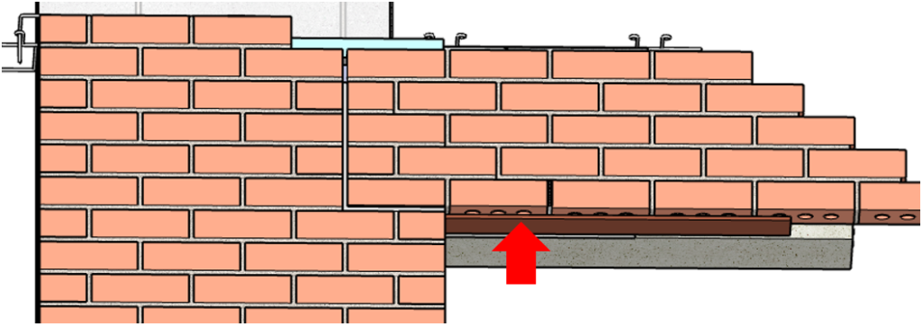 Figure 3 – Detail of lintel with a short leg
(Sketchup detail courtesy of IMI and modified by author)
(Sketchup detail courtesy of IMI and modified by author)
A. As you noted, this problem is twofold, structural, and aesthetic. There are at least two options that are possible.
- The first option is to weld an extension to the horizontal leg. There are several problems with that. It is very labor intensive, especially if there are many lintels to fix. The preparation of the exterior lintel to accept the weld and the grinding of the weld and paint touch-up are just as intensive. In addition, many masons do not do welding.
- The second option is to use near-surface reinforcement to create a masonry beam of the brick courses above the lintel. Figure 4 shows two layers of near-surface reinforcement placed into the masonry courses after the brick was already installed. The number of courses and the size of the reinforcement are dependent on the load on the lintel.
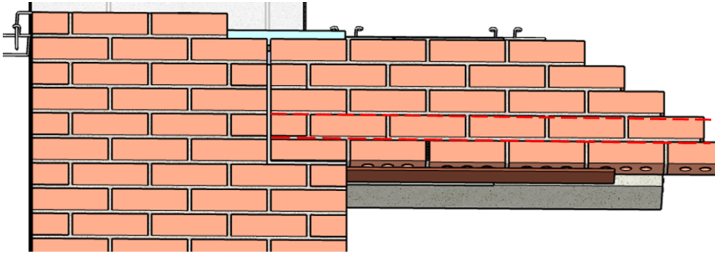 Figure 4 – Lintel with near-surface reinforcement
Near-surface reinforcement can be either metallic or FRP. The reinforcement is sized using beam theory. Generally, the reinforcement is sized to carry the total load and the lintel is considered to carry vertical shear and act as a stay-in-place form.
Figure 5 shows a section of the wall with metallic reinforcement in two courses.
The mortar is cut out to a depth of approximately 1-½ inches like repointing or stitching a crack. A ½” lift of pointing mortar is installed to the position of the reinforcement and the reinforcement (generally 6mm to 10mm stainless steel spiral rod by Helifix or Hohmann and Barnard) is pressed into place. The remaining mortar is installed in ½” lifts.
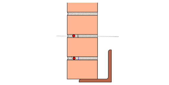 Figure 5 – Section showing near surface reinforcement
If FRP reinforcement is used, the first lift of pointing material is replaced with epoxy. After the FRP is embedded in the epoxy, the outer lifts are again mortar.
For the aesthetic portion of the repair, a stainless steel drip edge is added to cover the cores and sealed in place.
Summary:
- Near-surface reinforcement provides a solution that masons can perform to strengthen lintels without resorting to welding.
- The reinforcement can be sized using masonry beam design. FRP design can be performed using techniques from ACI 440.
Thank you again for following this column. Remember, by bonding, we get stronger! Keep the questions coming. Send them and your comments to info@masonrymagazine.com, with attention to Technical Talk. If you’ve missed any of the previous articles, you can find them online for Technical Talk, Bonding with Masonry at Masonry Design
David is a PE and SE with Biggs Consulting Engineering, Saratoga Springs, NY, USA (www.biggsconsulting.net), and an Honorary Associate Professor with the University of Auckland, NZ. He specializes in masonry design, historic preservation, forensic evaluations, and masonry product development.