Bonding With Masonry: Tech Talk Q4
Words: David Biggs
By David Biggs
This issue’s questions come from a Mason Contractor and an Engineer. What questions do you have? Send them to info@masonrymagazine.com, attention Technical Talk.
Q. A Mason Contractor writes that the drawings for many of the projects they bid on have masonry wall sections with solid bottom bond beams in the wall. The reinforced walls are either partially- or fully-grouted. How are we supposed to extend the reinforcement through these units? Figure 1 is an example of a partially grouted wall. The details do not show the vertical reinforcement, but it is 24 inches on center. The units are 16 inches long.
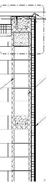 Figure 1 – Partially-grouted reinforced wall
A. The answer is you should not have to use solid bottom bond beams for these applications; there is an option. Open-bottom bond beam units are intended for use whenever vertical reinforcement is used (Figure 2). These units are typically standard units for which the webs are partially cut before shipping to allow the webs to be knocked out by the mason. A grout mesh is used to prevent the bond beam grout from flowing into the open cells of partially reinforced walls. For fully grouted walls, no mesh is required.
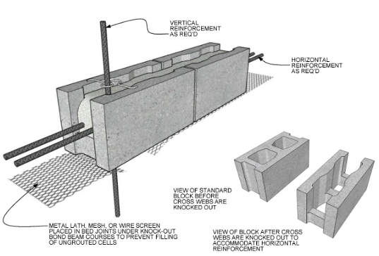 Figure 2 – Knock out bond beams (Courtest of the IMI)
Figure 3 shows a solid bottom bond beam with a cutout that allows vertical reinforcement. While cutting the units may be useful for partially grouted walls, it would be excessive for fully grouted walls and weaken the units. Engineers must specify the amount of cutting or coring required to get grout flow through the opening and properly position the bars. This option is not desirable whenever double offset bars are used either.
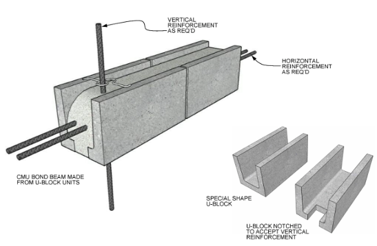 Figure 3 – Solid bottom bond beams with cutouts (Courtest of the IMI)
Summary
- Knock-out bond beams are preferred for use in reinforced masonry walls. Grout stop is available commercially for partially grouted walls.
- Cutting or coring solid bottom bond beams can restrict grout flow and weaken the units.
Q. An Engineer writes that she designs loose steel lintels to support the brick veneer in a cavity wall. Now she has a project in a high seismic zone. She asks why standard masonry details don’t require the loose lintel to be anchored to the backup of either cold-formed metal framing or CMU to resist out-of-plane forces from seismic loads or high wind.
A. Thank you for bringing up this topic. You are correct in that loose steel lintels are typically not anchored in standard masonry details. Figure 4 is one such standard detail.
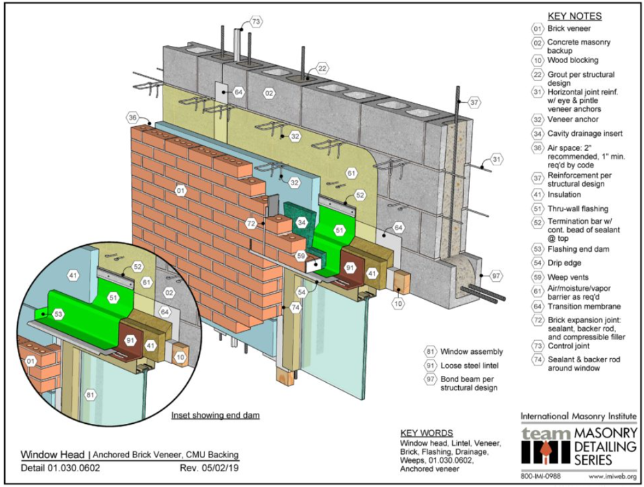 Figure 4 – Window Head Detail (Courtesy of the IMI)
BIA TECHNICAL NOTE 28B, Brick Veneer/Steel Stud Walls states “Lintels should be installed over all masonry openings unless the brick is self-supporting. Lintels can be loose steel angles, stone, precast concrete, or reinforced masonry. They should bear a minimum of 4 in. (102 mm) on brick on each side of the opening and should be sized to carry the brick veneer above them. For further information on lintels, refer to Technical Note 31B.”
Traditionally, loose lintels have been just that, loose. They clear span the opening for vertical support of the veneer, are self-supporting and usually rely on friction at their bearing to resist out-of-plane movement. Despite some designers using bearing pads under the lintel bearings which may reduce the frictional value of the bearing, out-of-plane lintel movement has not been reported.
How do we explain this? The easy answer is that the veneer ties that surround the opening at the head of the openings and jambs retain the veneer such that there is little lateral load placed on the lintel that could cause movement. However, it’s also important that the window or door below the opening is not anchored intentionally or otherwise to impart lateral loads on the lintel.
Engineers and architects are not limited to historical details. Each project should be evaluated for the specific details. Based on that logic, I have anchored lintels to the structural backup on various projects, and that anchorage is not only at the bearing ends. The lintel anchorage we are discussing should not be confused with the anchorage that applies to shelf angles. Shelf angles are usually bolted or welded to the backup and the backup supports both the vertical and lateral loads placed on the shelf angle. For example, Figure 5 shows a typical shelf angle on a concrete frame. The shelf angle only free spans between anchors.
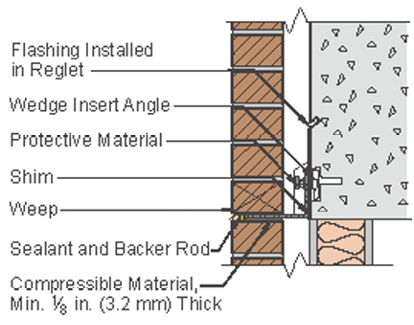 Figure 5 – Taken from BIA Technical Note TN 28B | Brick Veneer/Steel Stud Walls (Courtesy of BIA)
For loose lintels, while we use anchors to attach the lintel to the backup, their function may be more appropriately defined as “restraints”. So, under what conditions might we want to restrain a loose lintel and how might we detail the restraining anchor?
- Remember, loose lintels are free-spanning and are intended to carry the vertical load over the opening. Any anchor to the backup should therefore not restrain vertical movement. A bolted connection with vertically slotted holes in the lintel angle is typically used.
- Figure 6a shows a loose veneer lintel detail from the BIA used with CFMF backup. Note that this detail has jamb bricks that return and enclose the cavity at the window level; the window frame is set back to the CFMF. This jamb provides full bearing support for the angle. If the jamb brick does not fully return as in Figure 6b (an authored modified version of Figure 6a), the angle only bears on a portion of the jamb. The engineer should check the bearing stresses closely due to eccentricity.
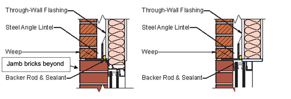 Figure 6a Figure 6b
Figure 6 – Section taken from BIA Technical Note TN 28B | Brick Veneer/Steel Stud Walls (Courtesy of BIA)
- Notice that the compression portion of the vertical leg of the angle is in the cavity and is unbraced. That is the first reason for adding lateral restraint, to reduce the unbraced length in flexure. The longer the span, the greater the need for intermittent restraint. AISC provides design criteria.
- A second reason to restrain the angle is evident from the loading on the angle as shown in Figure 7. Recognizing an angle’s shear center (line at which vertical load will not create torsion) is at the vertical leg, the vertical load of the veneer produces torsion on the section (T = V x e in-lbs/ft).
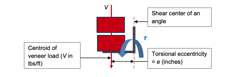 Figure 7 – Loading on lintel angle
AISC provides criteria for analyzing single angles for torsion (Steel Design Guide Series 9, Torsional Analysis of Structural Steel Members, Seaburg and Carter, c.2003). To reduce or minimize torsion, the angle can be restrained by bolting the vertical leg horizontally to the backup.
- Finally, angle restraint can be provided in high seismic zones or for high winds to add redundancy against out-of-plane movement. This lessens the stress on the surrounding veneer anchors.
- The detailing of the lintel restraint (anchor) is shown going into a CMU beam in Figure 8. (The detail can be modified for CFMF and structural steel). The angle has a vertical slot to allow lintel deflection and brick growth without loading the backup. The bolt is set at mid-height of the slot and double-nutted to restrain compression and tension. The nuts should not be tightened or the bolt will not slide in the slot. The horizontal restraint forces must be included in the design of the backup.
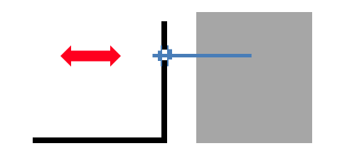 Figure 8 – Lateral restraint of lintel angle
- The restraint anchors must be designed. Based on the loads and angle selected, the design spacing is typically 2 to 4 feet on center and at the ends.
Summary
- Most loose lintels have a short span and do not require restraint against lateral loads.
- The details for each project should be evaluated to ensure the lintel is adequately braced against flexural compression, torsion, and lateral movement.
- Restraining anchors for loose lintels should restrain only lateral forces and movement, not vertical.
Thank you again for following this column. Remember, by bonding, we get stronger! Keep the questions coming. Send them and your comments to info@masonrymagazine.com, with attention to Technical Talk. If you’ve missed any of the previous articles, you can find them online for Technical Talk, Bonding with Masonry at Masonry Design (https://www.masonrydesignmagazine.com/?s=biggs).
David is a PE and SE with Biggs Consulting Engineering, Saratoga Springs, NY, USA (www.biggsconsulting.net), and an Honorary Associate Professor with the University of Auckland, NZ. He specializes in masonry design, historic preservation, forensic evaluations, and masonry product development.